Journal of Civil Engineering and Environmental Sciences
Accurate Analysis of Stand-up Time Rock Collapse When Inlet Tunnel Excavation is Carried out in there are Cracked and Broken Rock Formations and a Poorly Silty-clay Soil Profile
Munirwansyah1*, Reza P Munirwan2 and Surya Dharma3
2Lecturer at the Department of Civil Engineering, Faculty of Engineering, Syiah Kuala University Banda Aceh 23111, Indonesia
3Masters Student, Department of Civil Engineering, Faculty of Engineering, Syiah Kuala University Banda Aceh 23111, Indonesia
Cite this as
Munirwansyah, Munirwan RP, Dharma S. Accurate Analysis of Stand-up Time Rock Collapse When Inlet Tunnel Excavation is Carried out in there are Cracked and Broken Rock Formations and a Poorly Silty-clay Soil Profile. J Civil Eng Environ Sci. 2024;10(2): 054-060. Available from: 10.17352/2455-488X.000084Copyright License
© 2024 Munirwansyah, et al. This is an open-access article distributed under the terms of the Creative Commons Attribution License, which permits unrestricted use, distribution, and reproduction in any medium, provided the original author and source are credited.The condition of the rock formation and the poor stability of the type of soil mass (problematic soil) in the tunnel excavation route greatly influence the achievement of the collapse (stand-up time) that will occur. The thickness of the overburden pressure above the tunnel opening is often difficult to meet, so in the inlet zone as well as in the out-let zone, slope collapse often occurs and disrupts the work implementation schedule. On the slope of the inlet excavation location, there are also silt formations with outcroppings. Rocks from small to large sizes and there are even rock masses that are cracked so that the quality or strength of the rock is unstable when exposed to the equipment used when tunnel excavation work is carried out. This research method was carried out using an approach that corresponds to the Rock Quality Designation (RQD) value with the Rock Mass Rating (RMR) value which will provide a classification of rock classes and excavation methods. The data used in this research is rock data at the tunnel inlet of the Rukoh Dam Steering Building. From the RQD and RMR data and soil physical properties obtained in this research, analysis was carried out using the empirical approach introduced by Bieniawski. The results obtained from the in-situ test drilling work, the results of which were stored in the core box at the tunnel inlet, obtained an RQD value equal to 32.5% and an RMR value equal to 15. The RMR value shows that the rock at the tunnel inlet falls into the very category poor. With a tunnel opening as wide as 6.60 M, the stand-up time at the tunnel in-let is less than 30 minutes.
Introduction
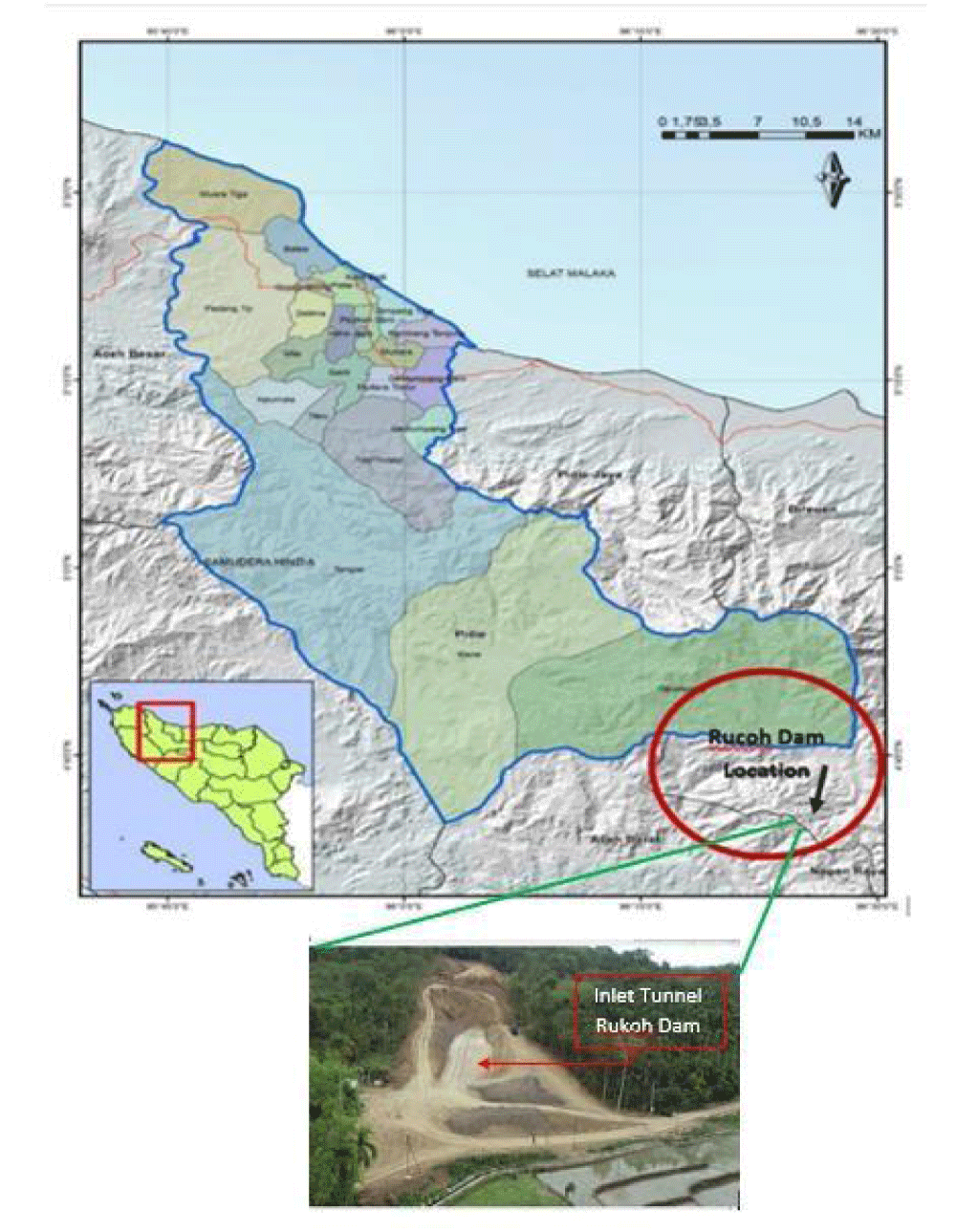
This dam is called the Rukoh Dam which is the name of the village in the Aceh province on the island of Sumatra where this dam was built, as shown in Figure 1. The Rukoh Dam is a replacement building for the planned construction of the Tiro Dam in another location which could not be carried out. The existence of the Rukoh Dam can increase rice production in the Pidie and Pidie Jaya districts which are part of the Greater Baroe Irrigation Area which has a service area of 11,900 ha, where currently not all land can be served for two planting seasons. With the Rukoh Dam, farmers’ productivity will be able to increase and the planting index will increase to 300%.
The Rukoh Dam Steering Building Project aims to supply the needs of filling the Rukoh Dam so that the filling time at the Rukoh Dam can be done faster. One of the scope of work in the Rukoh Dam Steering Building Construction project is the construction of a tunnel in the form of reinforced concrete construction with a horseshoe type along 950 meters with a tunnel diameter of 6.60 meters wide. This tunnel will be passed by water with a discharge of 12 m3/sec. to supply the needs of water replenishment at the Rukoh Dam, where supply to the Rukoh Dam is carried out during floods in the Kr. Inong river.
The data used in this analysis are the results of core box and laboratory testing on samples of soil mechanics investigation activities in the tunnel inlet, where the test results show that the main rock in the tunnel inlet is silty soil and a multiple body rock system.
The condition of the geotechnical profile in the tunnel location, which is dominated by silty-clay soil and rocks, has the property of easily experiencing moisture loss due to exposure to the weather. With this condition of the rock, the excavation method along the tunnel is very important to be analyzed and studied further, to facilitate the implementation and security against collapse during the excavation process.
Literature
This tunnel is a closed passage that connects two open sides or one open side with the aim of certain objects. This tunnel with two open sides is a water channel tunnel, penetrating both sides open.
Based on the materials used in tunnel construction, there are 3 different types of tunnels, Raharjo (2004), namely:
1. Close Dig Tunnel (Cut and Cover)
This tunnel was built by digging a large hole and building a tunnel structure in the dug hole. For the materials that make up this tunnel, pre-cast concrete is used, called a box culvert. This method can only be used if the tunnel is built at a shallow depth and excavation from the ground surface is possible.
2. Rock Tunnel
Rock tunnel construction is carried out on massive rocks using drilling or blasting methods. Rock tunnel construction is generally easier to carry out compared to soft earth tunnels because rock has higher stiffness and stability so the reinforcement required is simpler.
3. Soft Ground Tunnel
This tunnel passes through soft soil layers such as clay, sand, or soft rock. This type of material tends to collapse during the excavation process, so a strong wall or roof is needed as protection, Munirwansyah and Suwandi [1]. The technique commonly used is Shield Tunneling which uses a Tunnel Boring Machine (TBM), Bieniawski [2].
4. Rock mass rating
To calculate Rock Mass Rating (RMR) value accurately has to combine several variables that are found in the field to make it easier to describe existing rock classes. In addition, this system is the first to allow the estimation of rock mass properties, such as deformation modulus, thereby guiding in determining accurate temporary support and pay attention to tunnel openings and rock failure time (stand-up time) when digging tunnel holes.
There are 5 (five) parameters commonly used in determining rock mass classes using the RMR system, namely:
- Uniaxial Compressive Strength (UCS) of rock materials
- Rock Quality Designation (RQD)
- Distance of discontinuities (spacing of discontinuities)
- Condition of discontinuity
- Groundwater conditions
These five parameters are greatly influenced by observational assessments of rock outcrops, both obtained through core boxes and direct observations in the field during excavation. The five parameters are as shown in Tables 1-5, Widjaja, and Sundayo [3].
Another parameter that also influences the assessment in this RMR system is the orientation of discontinuities which is determined by the condition of the direction and slope (strike and dip orientation) of the soil or rock layer to the axle of the tunnel, the more perpendicular the slope of the layer is to the axle. The tunnel will get better, and vice versa.
Apart from that, the orientation of discontinuities is also influenced by the type of excavation work to be carried out (tunnel, foundation, or slope). The assessment of the orientation of discontinuities is shown in Table 6.
To make it easier to determine the assessment of the Rock Mass Rating (RMR) system, Bieniawski [2] has provided a table for determining the RMR value as shown in Table 7. Meanwhile, determining the rock class is based on the RMR value as shown in Table 8.
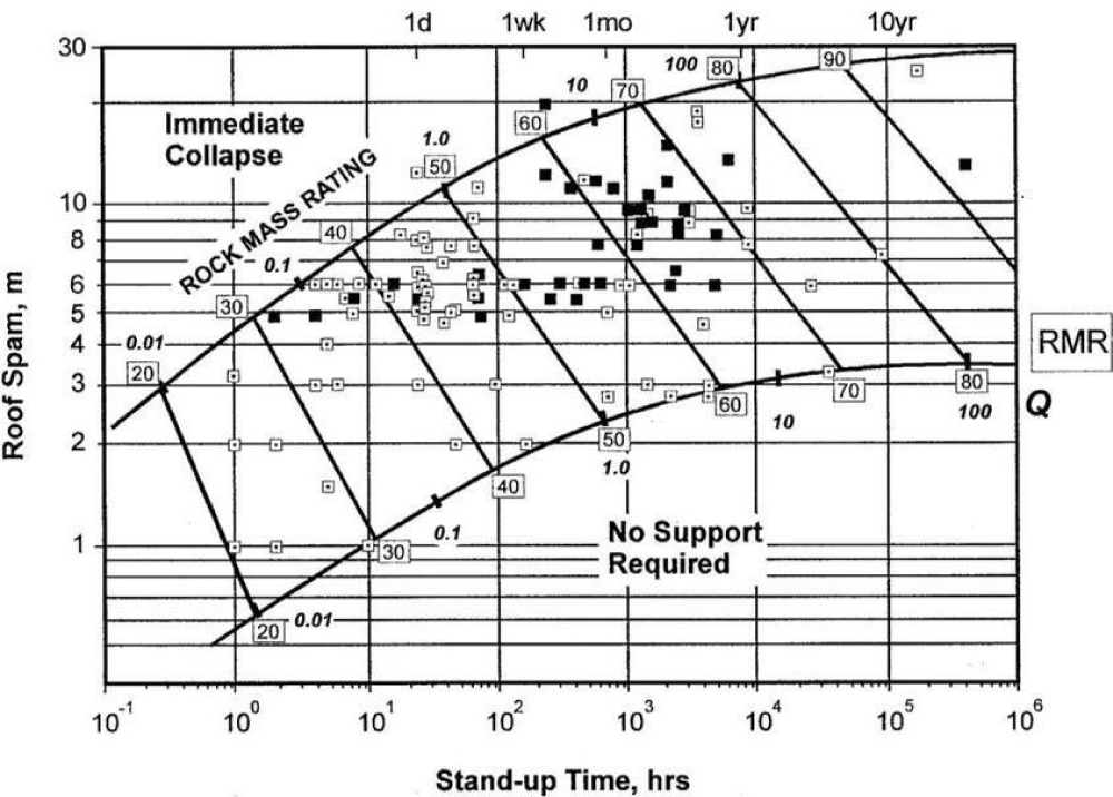
The RMR value of a rock also shows the level of stability of the rock itself. The higher the RMR value, the more stable the rock will be, and this condition will also influence and determine the excavation method chosen and the strengthening treatment that needs to be carried out. Furthermore, from the RMR value obtained using Table 8, as well as by determining the opening (excavation) of the planned tunnel, the stand-up time of the tunnel opening will be obtained. Where stand-up time itself is defined as the ability of a rock mass to support itself due to excavation activities before a collapse occurs. The relationship between the RMR value and the roof spam (excavation) opening in the tunnel itself means that the stand-up time value and rock mechanical property by N-SPT will be known, as shown in Figure 2 and Table 9.
Methodology
Excavation and Strengthening Methods for Tunnel Inlets depends from the results of the calculation of the RMR value, the rock class at the tunnel inlet will be obtained which will influence the excavation and strengthening methods. The higher the RMR value, the better the rock class and the easier the excavation process will be and it will not require a lot of support to strengthen the tunnel due to excavation before concreting. However, on the contrary, the smaller the RMR value, the more difficult the excavation process will be and a lot of support is needed to strengthen the tunnel itself.
Several excavation methods include blasting, breaker, digging, and ripping. The blasting and breaker system is generally carried out on rocks that have an RMR value above 40, while the digging and ripping system is carried out on rocks that have an RMR value below 40.
The greater the RMR value, the greater the stand-up time of the tunnel, so that strengthening the tunnel excavation does not require a lot of support, and in some conditions, no support is even needed until concreting is carried out. Meanwhile, if the RMR value is small enough, so that the stand-up time is very small, then strengthening due to tunnel excavation is something that needs to be considered to secure the work when the tunnel excavation is carried out. The reinforcement carried out is by installing rock bolt anchors, shotcrete, steel rib, forepoling, and concreting (lining).
Wrong methods due to Illegal interference with personal expertise in scientific fields have recently become quite a burden on work in the field and hampered the smooth implementation of methods in the field. The drilling method in the field by a geological expert of course aims to explore natural products such as drilling for coal, natural gas, geothermal energy, petroleum, and other natural products. Of course, it is different from drilling carried out by Civil Engineering personnel in the Geotechnics field who carry out sondir or drilling to find out the composition of the soil profile and its physical and mechanical properties as well as its shear strength and bearing capacity.
The wrong method intended was found in the results of this research, that the results of the detailed engineering design at the tunnel inlet excavation location were assumed to be rock, however in implementing the excavation no solid rock was found, but a rock fracture outcrop with poor Rock Quality Design (RQD) was found. And there is clayey silt which is very easy to slide when experiencing changes in water content and reduced overburden pressure, the thickness of the layer above is disturbed by its thickness. The method is not understood by a bunch of geologists who have no ethics and logic in mixing civil engineering work with geotechnical expertise. The wrong methods are revealed in this article so that in the future such embarrassing incidents are not repeated by gangs of unethical geologists this is also how we educate our geotechnical master’s students to be useful examples of cases of failure in the field and they dare to reject the expertise of their colleagues who do not appropriate to interfere with geotechnical civil engineering work.
Results and discussions
In this chapter, the results obtained from observations of the core box results and laboratory test results on rock samples at the tunnel inlet are described. From these results, the RQD and RMR values can be obtained and the value of the stand-up time due to the tunnel inlet opening can be determined.
The research results showing several laboratory test results and field investigations as described were due to errors in assumptions and were not carried out by civil engineering experts but were mixed up as academic crimes committed by other evil experts, Munirwansyah, et al. [4].
As described in the methodology above, it was proven to be very different after being carried out by civil geotechnical engineering master students.
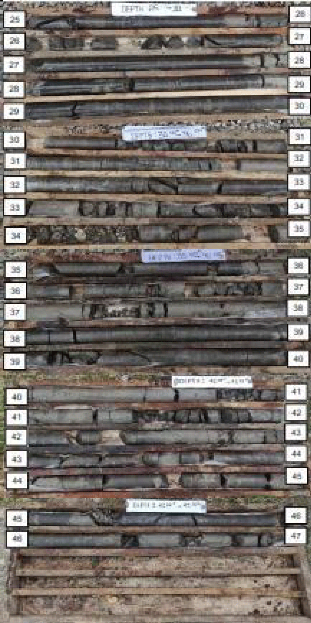
The results found were no soil index (GI) group parameter results, and no particle size analyzer was carried out, Munirwansyah, et al. [4]. It was proven, as shown in the core box in Figure 3, SNI - Indonesian National Standards [5] and [6]. Test Method for Determining the Plastic Limit and Soil Plasticity Index. National Standardization Agency. Jakarta.
That it was not a solid and stable rock, but had experienced multiple body rock systems, so it was not recommended for this location. When building a tunnel inlet, it needs to be shifted to another route whose location can be easily identified if DED is carried out by a geotechnical expert, it must not involve evil geology experts who usually conspire as in the case of planning the DED tunnel.
Rock Quality Designation
The Rock Quality Designation (RQD) value is determined by looking at the percentage of rock in the core box that is larger than 10 cm. Observations of the RQD values were carried out at a depth of 32–37 meters which is the dimension of the tunnel opening. The results of the Core Box at the tunnel inlet are shown in Figure 3, Terzaghi & Ralph [7].
Based on Figure 3 above and as previously stated, the bottom of the tunnel inlet is at a depth of 37 meters from the surface, if the diameter of the tunnel opening is 6.6 meters, then the RQD value at the tunnel inlet opening is 50, 65, 13.12, 30 and 25 with an average value of 32.5%. Based on Table 8, the rock class qualification at the tunnel inlet opening is poor. Meanwhile, the tunnel base at a depth of 38 meters has an RQD value of 40%, whereas with an RQD value of this size, the tunnel base is also in the poor rock class. In conditions like this, it is very dangerous to build a tunnel because it will cause workers, operators, and site engineers to be buried in collapsed soil quickly and landslides.
Rock Mass Rating
The input data used to determine rock class using the rock mass rating system (RMS) is data obtained from laboratory test results and also observations of rock conditions in the field. From table 10, the uniaxial compressive strength value is obtained, with values ranging from 4.74 – 6.67 MPa, with an average value of 5.705 MPa. From field observations of rock fractures, the spacing of discontinues was 50 mm. Apart from that, the presence of springs in the tunnel route also affects the RMR value itself. By using the rock class classification based on Bienewski [2], an RMR value of 15 was obtained with the rock class very poor rock as shown in Table 9.
Determination of the RMR value is carried out using table 7 by entering several parameters in the form of laboratory test results on the mechanical properties of rock at the tunnel inlet (UCS) as shown in Table 10.
Analysis of Excavation and Strengthening Methods for Tunnel Inlets From the description above, it has been stated that with an RMR value of 15, the rock class at the tunnel inlet is included in the poor rock class with a stand up time of less than 1 hour. This will certainly make it difficult to dig the tunnel inlet itself. Bieniawski [2] has provided several excavation and strengthening methods for tunnels based on rock class, as shown in Table 10.
Stand up time
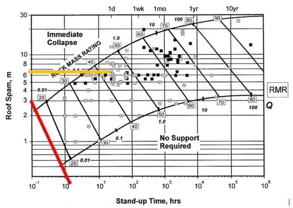
Furthermore, from the RMR value, and connected with the planned opening of the tunnel of 6.6 m, stand up time for the excavation will be obtained as shown in Figure 4, which shows that the excavation at the tunnel inlet will experience collapse as a result of the tunnel opening. Alone, Wesley, L.D. [8-11].
Based on the results obtained as shown in Figure 4, it shows that with a tunnel opening of 6.6 m and an RMR value of 15, it is found that the excavation at the tunnel inlet will collapse quickly (less than 1 hour).
From Table 11 above, shows that for the poor rock class, the recommended excavation method is to dig to a depth of 0.5 - 1.5 m at the top of the tunnel and continue by installing temporary support such as shotcrete after excavation. Followed by installing rock bolt anchors 5-6 meters long at a distance of 1-1.5 meters on the roof (crown) and walls of the tunnel as well as installing wire mesh. Shotcrete is carried out on the roof 15 -20 cm thick, on the walls 15 cm thick, while on the face of the excavation, it is 5 cm thick. then, it is necessary to install steel ribs (H beam) with a distance of 0.75 m and also stiffeners on the steel rib legs (struth) to prevent lateral forces that occur which burden the steel rib. If the rock condition is quite weak, it is necessary to install forepoling on the roof to prevent collapse during excavation [12-21].
Authors Gratefully Acknowledge Assistance from the Syiah Kuala University (USK) And the Ministry of Research, Technology, And Higher Education Indonesia, for the Professors Research Scheme PP 2024 LPPM-USK, We’d like to thank the Rukoh Dam Project For the secondary soil investigation data. Also, we’d like to thank the Master’s and Doctoral Students of the Civil Engineering-Geotechnic Division, FT-USK for their timely Inclusion and help during this research.
- Suwandi, Munirwansyah, Yunita H. Comparative analysis of shear strength test results of stabilization of Paya Tumpi soft clay and other quarries with Burni Telong volcanic ash. Wih Pesam. 2024;476:9. Available from: https://doi.org/10.1051/e3sconf/202447601016
- Bieniawski ZT. Engineering rock mass classifications. 1989.
- Widjaja B, Sundayo P. Alternative determination of liquid limit and plastic limit with three cone weight variations using the Lee and Freeman method (2009). J Civil Eng. 2016;14(1):62-7.
- Munirwansyah M, Munirwan RP. Lime-clay stabilization to modify the characteristic of mechanical properties and reduce the swelling of sub grade. In: International Conference of Engineering and Science for Research and Development; 2016; Vol. 1, No. 1. Available from: https://www.researchgate.net/publication/331397578_Lime-Clay_Stabilization_to_Modified_the_Characteristic_of_Mechanical_Properties_and_Reduce_the_Swelling_Sub_grade
- SNI (Indonesian National Standards) 1966:2008. Test method for determining the plastic limit and soil plasticity index. National Standardization Agency; Jakarta; 2008.
- SNI (Indonesian National Standard) 1964-2008. How to test soil specific gravity. National Standardization Agency; Jakarta; 2008.
- Terzaghi K, Ralph P. Soil mechanics in engineering practice. Jakarta: Erlangga; 1987.
- Wesley LD. Soil mechanics for soil sediments and residues. Yogyakarta: Andi Publishers; 2010.
- ASTM. ASTM D2166 - Standard test method for unconfined compressive strength of cohesive soil. American Society for Testing Materials; 2006.
- ASTM. ASTM D5731 - 95 Standard test method for determination of the point load strength index of rock. American Society for Testing Materials; 2006.
- Sumatran River Basin Agency I. Final geological report on Rukoh Dam steering building. 2023.
- Barton N, Lien R, Lunde J. Engineering classification of rock masses for the design of tunnel support. Rock Mech. 1974. Available from: https://doi.org/10.1007/BF01239496
- Dearman WR. Engineering geological mapping. 2013.
- Giffari DA. Numerical modeling of the stability of the evacuee tunnel - Meninting Dam spillway in West Lombok Regency. Department of Civil Engineering, Faculty of Engineering, University of Mataram; 2023.
- Griffiths JS. Engineering geological mapping. University of Iowa; 2015. Available from: http://egsp.lyellcollection.org/
- Hung J. FHWA technical manual for design and construction of road tunnel - Civil elements. 2009. Available from: https://rosap.ntl.bts.gov/view/dot/50019
- PUPR. Guidelines for excavation planning methods and road tunnel strengthening systems in mixed rock soil media. Indonesia; 2015.
- SNI (Indonesian National Standard) 2813:2008. How to test the direct shear strength of consolidated and drained soil. National Standardization Agency; Jakarta; 2008.
- Saptono STIADP. The influence of the NATM excavation method on the stability of the Cisumdawu double tunnel in Sumedang Regency, West Java Province. J Min Technol. 2019;5(1).
- Simbolon GO. Analysis of the buffer system in the Lau Simeme Dam project evasion tunnel, Sibiru-Biru District, Deli Serdang Regency, North Sumatra. Faculty of Engineering, Medan Area University; 2022.
- Telford WM, Geldart LP, Sheriff RE. Applied geophysics: Vol. second edition. 1990. Available from: https://books.google.co.in/books/about/Applied_Geophysics.html?id=Q8ogAwAAQBAJ&redir_esc=y
Article Alerts
Subscribe to our articles alerts and stay tuned.
 This work is licensed under a Creative Commons Attribution 4.0 International License.


 Save to Mendeley
